Carbon Capture (Utilization) And Storage
Main objective of CCUS projects is the reduction of greenhouse gas emissions (CO₂) from heavy industries with the intent of mitigating the effects of climate change.
CCUS - Process of capturing high concentrations of carbon dioxide (CO₂) emitted by industrial activities such as natural gas production facilities, coal-fired or biomass power plants, chemical plants, and any other industries generating CO₂. The captured CO₂ is transported and stored in an underground geological formation (carbon sequestration) for centuries or millennia in the case of CCS, or recycled for further usage in the case of CCU projects.
Carbon Capture and Utilization (CCU) projects, like CO₂ injection for EOR purposes, could be considered as Carbon Neutral projects. Part of the CO₂ captured could be produced back at the end of the process. The final balance results in no additional CO₂ generation.
Sequestration (Storage) Clusters
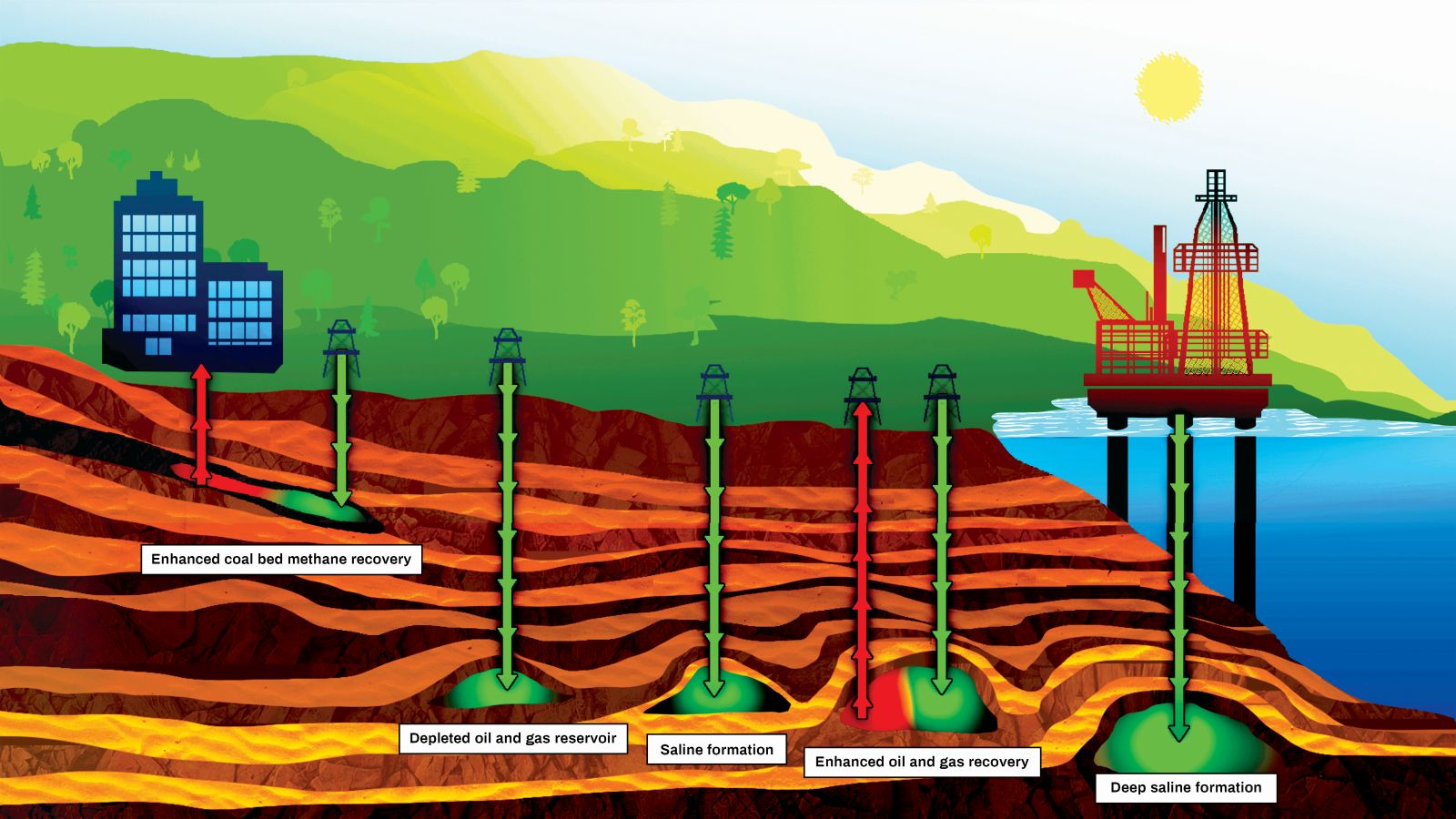
CO₂ storage locations typically are:
- Depleted Oil or Gas fields that are no longer viable or economic for production. The drivers for using these are the existence of surface facilities and the information availability concerning:
- Storage capacity
- Reservoir compartmentalization
- Injection conditions
- Cap rock sealability
- Saline formations that refer to any saline water bearing formation (non-potable). The saline formation must be sealed by a caprock for permanent storage.
- No risk of CO₂ leakage through un-properly abandoned wells.
Additional types of underground formations for geologic carbon storage have been investigated. These are:
- Non mineable coal seams which were never exploited
- Basalt formations
- Organic-rich shales
Fluids To Be Injected
Captured CO₂ can contain impurities depending upon its origin (associated with natural gas versus combustion byproduct)
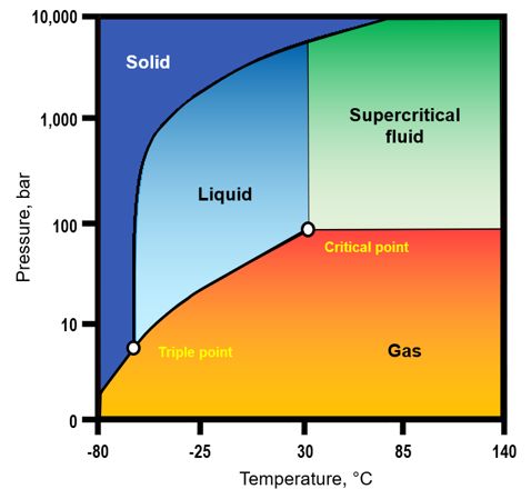
Depending on pressure and temperature conditions at well head and along the wellbore, the injected fluid could be gas, liquid or dense phase (supercritical - highly compressible fluid that demonstrates properties of both liquid and gas).
The fluid to be injected can vary from/to:
- Clean CO₂ – Dry (negligible water content) or with some associated water.
- Contaminated CO₂ – Presence of impurities or corrosive elements, such as:
- H2S (Hydrogen Sulfide)
- O2 (Oxygen)
- NOx (Nitrogen Oxides)
- SOx (Sulphur Oxides)
Injection Phases and Potential Risks
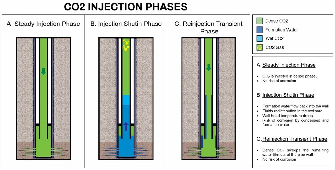
There is a risk of formation water flowing back into the wellbore during injection shut-in periods. In this case, formation water composition will affect the corrosion aggressiveness of the bottomhole environment.
- CO₂ + Formation water (@ bottomhole) ð Potential (*) Risk of Stress Corrosion Cracking of CRA’s
- CO₂ + Condensed water (@ wellhead) ð Potential (*) Risk of Sulfide Stress Cracking
(*): depending upon the well environment and fluids composition.
Tubing Connection behavior under CCUS Loads
CO2 injection wells are expected to be subjected to relatively benign mechanical loads. On the other hand, temperature variations could represent unusual challenges, specific to CCUS applications:
- Sub-zero temperature, corresponding to CO₂ injection cycles
- Rapid temperature variations transient state
- Extreme cryogenic temperature, down to -80°C, corresponding to uncontrolled decompression

Material Selection
Input Data
The following information must be considered to properly assess the corrosiveness of the environment:
- Injection conditions
- Injection fluid composition
- CO₂, H2O, H2S, O2, NOx, SOx and any other element considered important
- Reservoir fluid composition
- Formation water composition
- Original Reservoir Gas composition in case of injection in a depleted reservoir
Experimental experience in CO2 containing environments
One of the critical Material Selection aspect for CCS/CCUS applications is that the injected CO₂ will drive the environment pH to very low levels (~ 2.5/ 3.0). This shall obviously affect any material exposed to the environment in terms of general corrosion as well as pitting/cracking behaviors These wells may need to be designed to withstand the expected corrosive environment for a considerable time span (50/100 years or more), thus increasing the criticality assessment.
In addition to the prior considerations, critical elements for Material selection in CCS/CCUS environment is the presence of contaminant like:
- Dissolved O2 (DO,)
- Impurity like NOx or SOx
Adverse effect of dissolved oxygen on materials in downhole applications has been extensively studied in the industry specifically in water handling systems. Super Duplex stainless steel (SM25CRW / UNS S39274 with PREN (*) > 40) has been the reference material used in the industry in oxygen saturated environment.
Recent studies performed by Nippon Steel on the effect of O2 in CO2 dominant environments carried out on Super Martensitic Stainless Steel (SM13CRS / UNS S41426) and Super Duplex Stainless Steel (SM25CRW /UNS S39274) (see Fig 1) have confirmed that:
- Super Martensitic Steel can suffer corrosion (general and pitting corrosion) starting from 1% vol of O2
- Super Duplex Steel did not suffer any corrosion attack with an oxygen concentration up 4% vol of O2
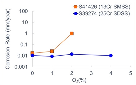
Fig 1: Immersion test – 130 bar CO2, 100℃, 5 wt% NaCl, 96 hours) with varying O2 concentration
On the other hand, little is known about the effects of combustion by products, like NOx and SOx, for downhole applications.
Recent studies performed by Nippon Steel have confirmed that even low concentrations , (around 0.02 % vol) of SO2 can be detrimental (increased corrosion rate) to materials like S13CR (UNS S41426), while Super Duplexes (UNS S39274) do maintain a stable corrosion rate in SO2 concentrations up to 0.5%.
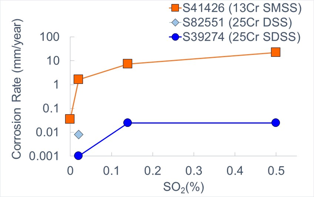
Figure 2. Immersion test - 130 bar CO2, 100℃, 5 wt% NaCl, 96 hours) with varying SO2 concentration
Therefore, for NOx, SOx effect on materials, additional studies are required to define the critical thresholds of these impurities on materials behaviors in CO2 dominant environments.
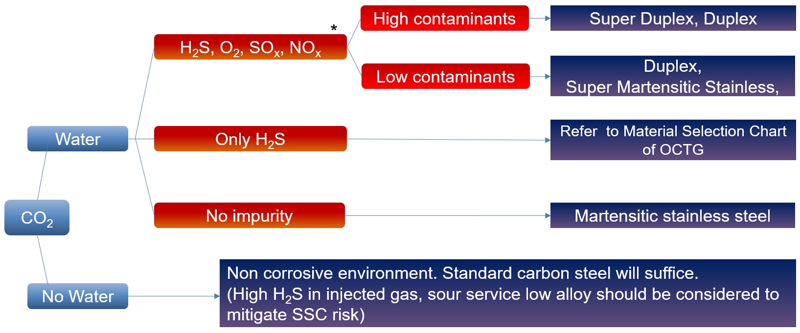
Material Selection workflow
This Material Selection concept provides a quick assessment of possible materials to be used for CCUS applications, based on generic parameters such as presence of water, H2S and impurities. Once the expected environment is clearly defined (fluid characteristics composition, well conditions, etc.), a fit for purpose material selection will be launched using as reference existing Nippon Steel corrosion data base and/or fit for purpose tests meant to define the most cost-effective solution for the application.
Connection Selection
Current industry standards addressing Premium connection validation (ISO 13679 and API 5C5) are based on downhole hydrocarbons production conditions, in a positive temperature environment range, up to 180°C.
CCS application, is not covered by these standards, while CO₂ injection brings in additional challenges to connection integrity related to sub-zero and rapid temperature variations.
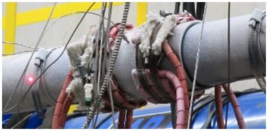
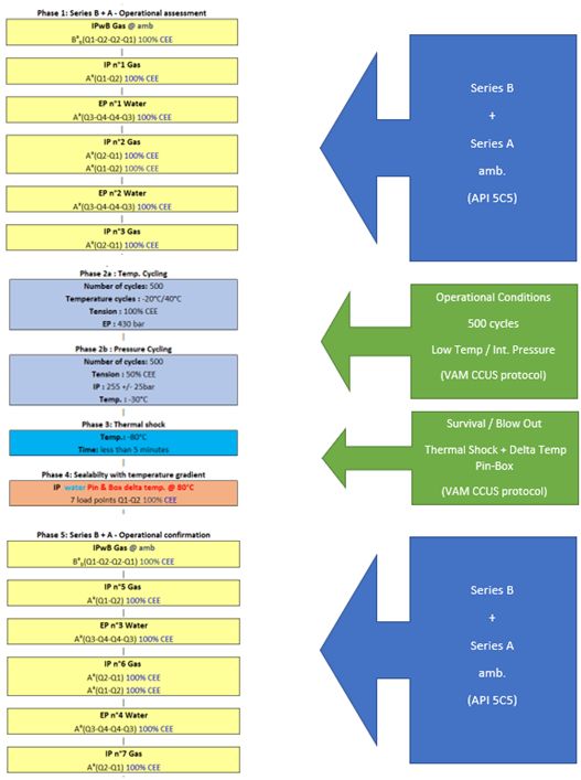
VAM® Research & Development (partnership established between Vallourec & Nippon Steel Corporation since 1985) analyzed the different CCS application loading scenarios, to establish additional connection technology requirements. VAM® developed a unique methodology of validation, based on ISO 13679 / API 5C5, with the addition of CCS low temperature load requirements to include:
- Functional validation of technological elements at low temperature (surface treatment adherence, lubricating system, …)
- Full scale sealability testing in CO₂ medium
- Subzero Thermal cycling (25 cycles between room temperature and -35°C)
- Thermal shock from operational temperature down to -80°C in less than 2 seconds
- Sealability under imposed temperature differential (~ 60°C), between pin and box
As a result, VAM® has designed & validated with CCS leading operators, a relevant qualification testing protocol along with fit for purpose test equipment, allowing to demonstrate VAM® Premium connections mechanical & sealing integrity. Concomitantly, VAM® successfully tested its latest technology connections to this CCS protocol, demonstrating that VAM® products are fit for CCS applications usage.
Prior experience in CCS projects
Nippon Steel has been involved in a number of CCS projects to support Material Selection process. Some of these are:
Large Scale CCS Project (Australia): naturally produced CO2 from offshore gas reservoirs, is separated at the onshore gas plant and re-injected into a giant sandstone formation two kilometers beneath Barrow Island, where it remains permanently trapped.
Offshore CCS Project (Norway): CO2 captured onshore, will be transported by newly designed ships, injected and permanently stored 2,600 meters below the seabed of the North Sea.